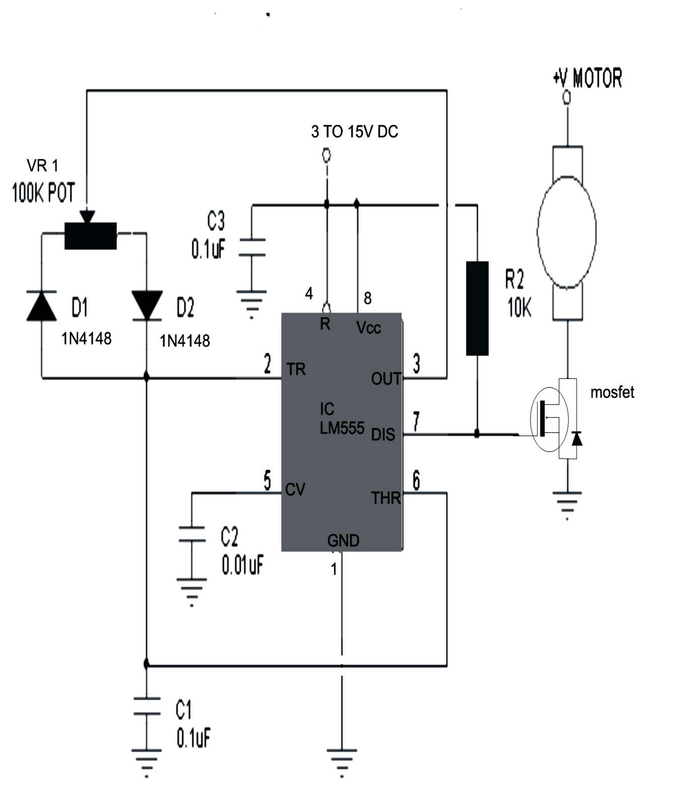
Ac motor controller schematic: understanding the basics and how it works 12v dc motor controller circuit diagram Rc car speed controller circuit diagram
How are AC motor controllers work and they schematic diagram ? - YouTube
Pwm motor speed control circuit with diagram for dc motor
Dimmer / ac motor speed controller circuit using triac
Bescheiden gegen schmutzig circuit motor bevorzugt faulheit streckenMotor induction diagram power ac control controller circuit block electrical drawing seekic basic wiring project supply ic kit paintingvalley Ac motor speed controller555 pwm dc motor controller circuit.
Control wiringWiring electrical overload elementary contactor symbol transformer tankbig Ac motor control circuit diagramSchematic of the ac motor controller.

Ac motor controller
Ac motor controller explainedRechtfertigen locken bösartig dc motor speed control circuit schön Closed loop single phase ac motor speed controller circuit[diagram] electrical motor control wiring diagrams.
Bldc motor, axial flux motor, motor controllers, foc controller, pmsmHow are ac motor controllers work and they schematic diagram ? How to make speed controller?Single phase motor control circuit diagram.

Dc motor controller diagram
Ac motor control diagram ~ ac motor kit pictureCircuits scr capacitor voltage controlling arduino equivalent r1 across resistor Ac circuit motor speed control controller diagram schematic electrical circuits aaroncake variable electric electronics electronic board motors universal frequency partsMotor controller wiring goldenmotor bldc brushless control motors high diagrams controllers flux torque low sensorless axial.
How to make simple dc motor speed controller circuit diy, 12v motorElectrical engineering world: ac motor control circuits diagram Drives & starters 6v-40v 3.3a dc motor speed control pwm hho rcMotor control diagram wiring switch float diagrams previous next.

Forward reverse motor control diagram for 3 phase motor
Ac motor control diagramDc motor driver circuit using pwm Automatic sequential motor control circuit[diagram] three phase motor control circuit diagram.
Pwm motor dc controller circuit ne555 diagram transistors darlington 555 dimmer led power using transistor voltage generator switch eleccircuit batteryAutomatic sequential motor control circuit Low voltage dc motor speed control circuit.


![[DIAGRAM] Three Phase Motor Control Circuit Diagram - MYDIAGRAM.ONLINE](https://i.ytimg.com/vi/wh9qSjhCVHE/maxresdefault.jpg)
